 |
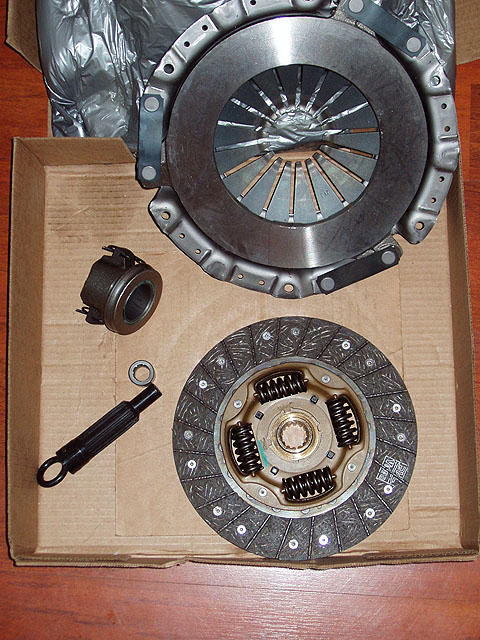
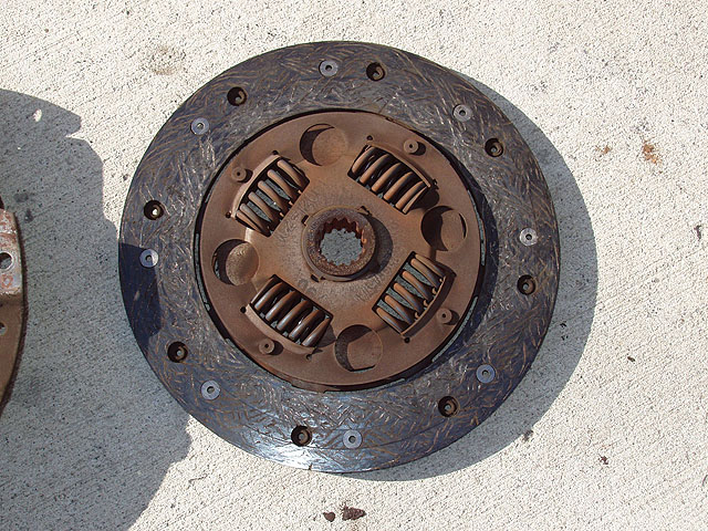
1. Components of the clutch kit. Average price on the street (catalog, parts store, or even Jeep dealer - they all sell the same kit with the same parts): about $125.00. From top clockwise: Pressure Plate, Clutch Disk, Pilot Bearing and Alignment Tool, Release (throwout) Bearing |
 |
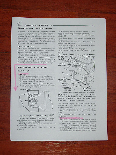
2. Jeep Service Manual Excerpts. About 6 steps into this we started finding errors, for instance after removing the transfer case and setting it on the ground, a few steps later we were told to remove the transmission/transfer case assembly (???). To make matters worse, this nearly 15 hour procedure was reduced down to about 3 pages of actual steps with very little illustration, hence the need for this writeup. The remainder of the procedure has nearly every major step illustrated with at least 1 or more up-close-and-personal photos. |
 |
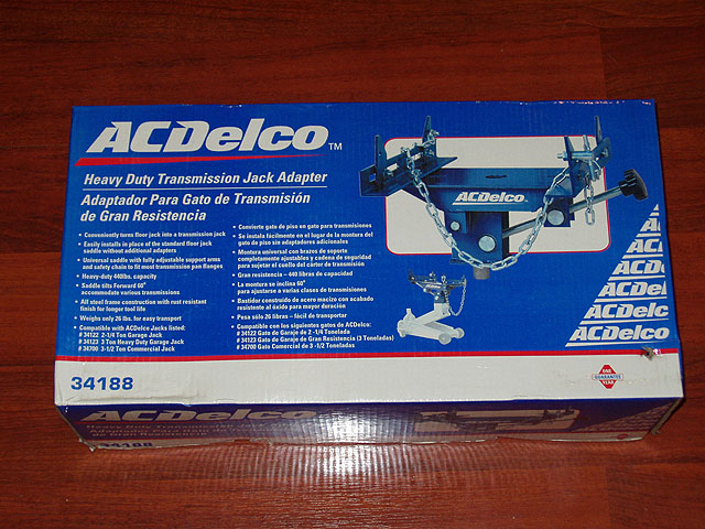
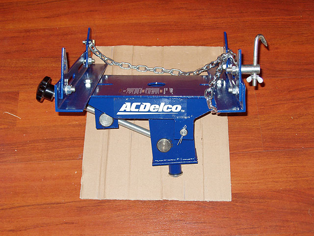
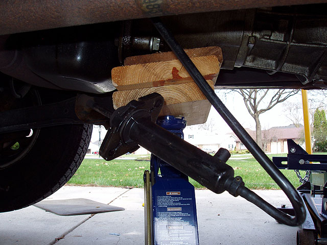
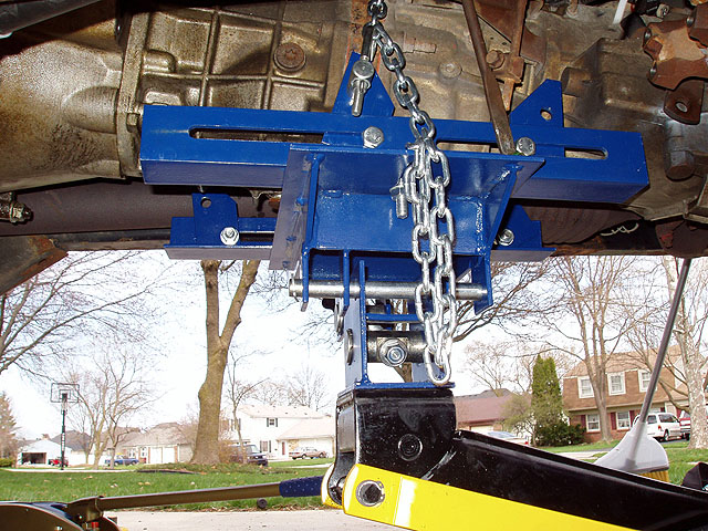
3. The floor jack adapter we used for handling the transmission/transfer case assembly. This is a MUST HAVE for this job along with the floor jack. The trans/transfer case is large, and unwieldy. This tool, $40 is an investment and will pay off again if you ever have to remove your transfer case to add an SYE after you lift your Jeep |
 |
4. The floor jack adapter comes in a kit of parts. Here it is assembled |
 |
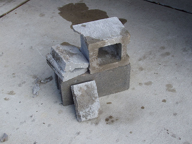
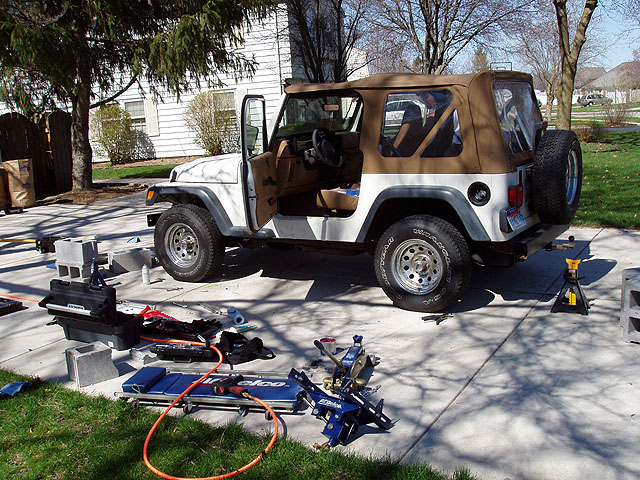
5. Here's what could happen if you decide to use cinder blocks solely to support the Jeep and get it high enough to work under it. This happened when we were first jacking it up and the frame came down on the side of the vertical web of the block. We decided to use jack stands to support the Jeep and cinder blocks under the frame as a backup. |
 |
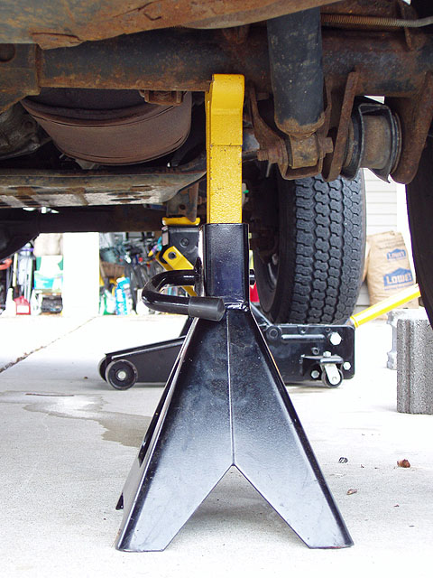
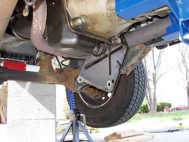
6. Jack and block the vehicle to a height of 3 standard cinder blocks between the bumpers and the ground. Don't rush this, you'll be spending a long time underneath and you need enough room to work. This represents the minimum needed. We placed jack stands on the axles as close to or on the spring perches as we could. This keeps all the supports out of the way of where you need to be working. |
 |
 |
 |
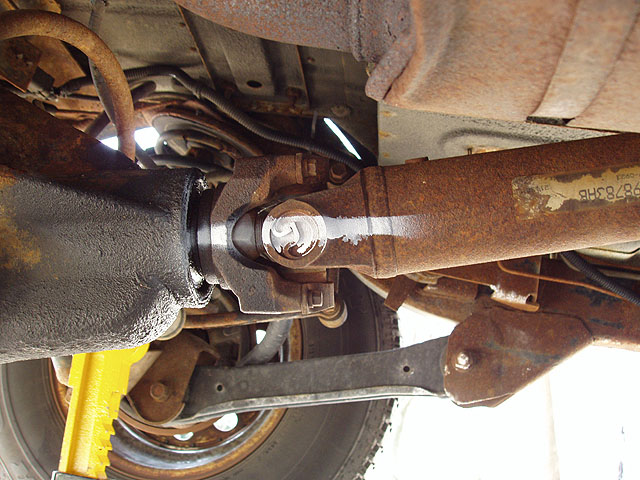
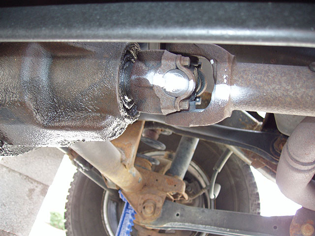
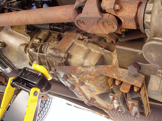
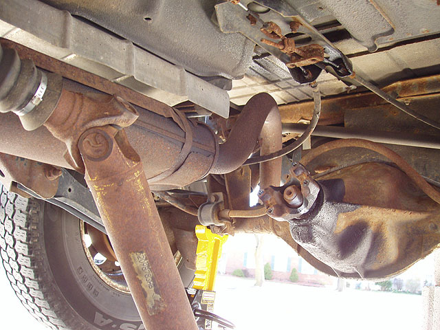
| 7. Mask a stripe on rear axle pinion yoke, rear axle u-joint and rear yoke of rear driveline. Spray with white paint to mark orientation, remove 4 yoke bolts & two yoke straps and set aside. |
8. Dislodge rear propeller shaft & let hang down. We did not remove the rear propeller shaft from the transfer case and thus did not need to drain the transfer case or trans, though with the mileage on this jeep we did |
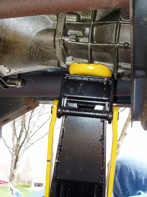
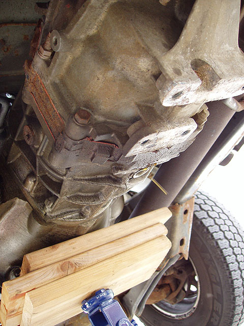
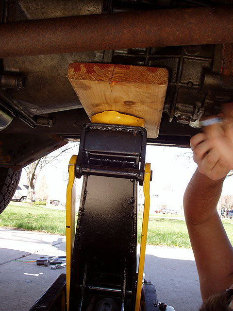
9. Support the trans/transfer case assembly with additional jack or jack stand and wood block on trans body casting which forms a "+" on the forward end of the trans. This will relieve the weight so that the skid plate can be removed. |
 |
 |
 |
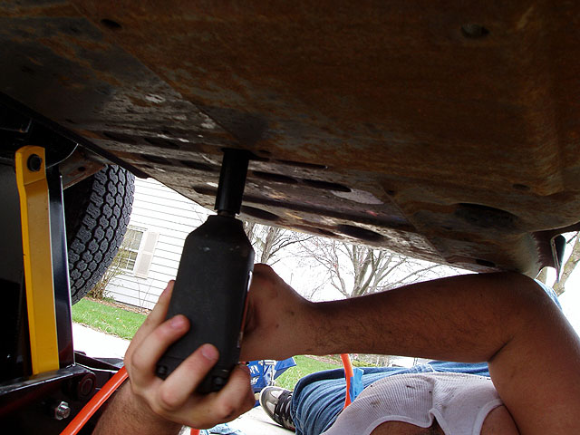
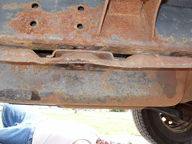
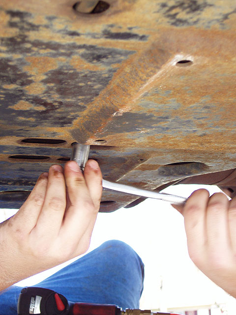
| 10. Unbolt the 4 crossmember-to-skid-plate nuts. |
11. Unbolt the 6 skid-plate-to-frame bolts, remove skid plate and set aside. |
12. Remove the transfer case skid plate support (sometimes called the cross member), and set aside. |
 |
 |
 |
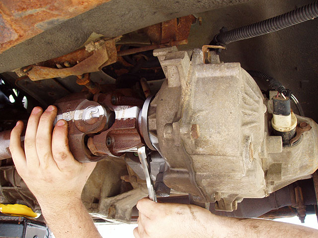
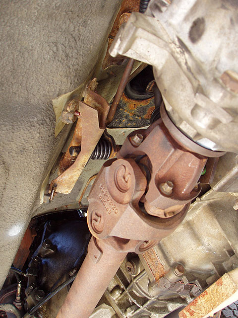
| 13. Repeat marking procedure for front propeller shaft at the double caridan CV joint (and yes, it is a CV joint!) where it goes into the transfer case. |
14. Remove (4) 1/4 bolts at the transfer case yoke. |
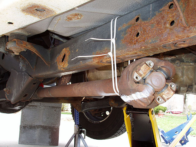
15. Disconnect the front drive line & zip tie it to the driver side frame with 2 zip ties (in case one breaks). |
 |
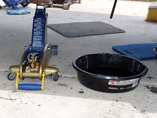
16. This is a good time to drain and cap the transfer case and transmission and cap it in preparation for refilling. |
 |
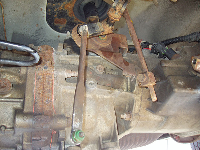
17. We jockeyed the jacks around a bit and supported the trans forward of the transfer case with wood blocks and a second jack. This allowed us to work to remove the transfer case linkage, shift tower retainer and wiring harnesses prior to placing the transmission jack adapter and removing the trans/transfer case assembly. |
 |
18. Pop the transfer case shifter linkages out of their mount on the tub bracket and let it hang down out of the way. This frees up the half of the transfer case shift linkage so the trans/t-case assembly can be removed. |
 |
 |
 |
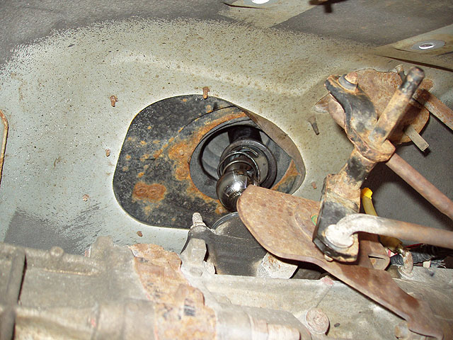
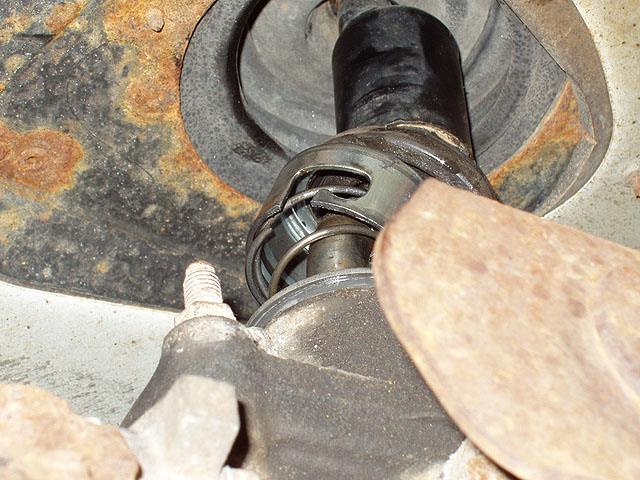
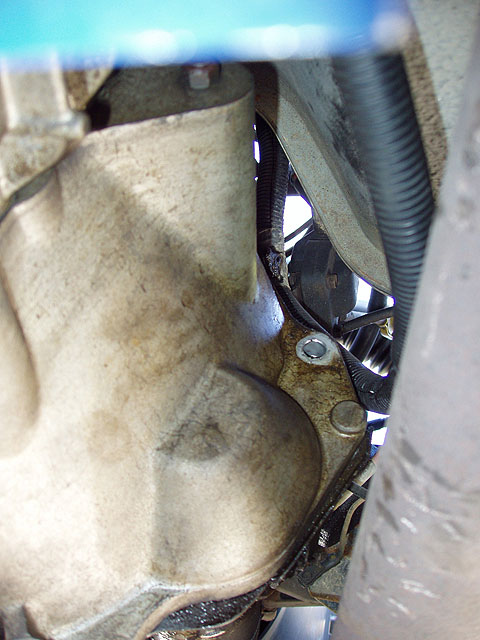
| 19. Remove the 2 slave cylinder stud/bolts, pull out slave cylinder & zip tie to frame along side but on top of front propeller shaft previously tied. |
20. Remove two crankshaft position sensor bolts. |
21. Carefully slide the CPS out of the rubber grommet. |
 |
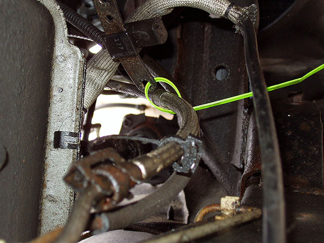
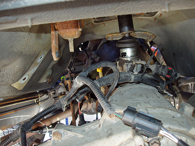
22. Zip tie to fuel line to keep it out of the way. If you break a wire on this, your engine won't run, so we keep it safely out of the way during the rest of the procedure. |
 |
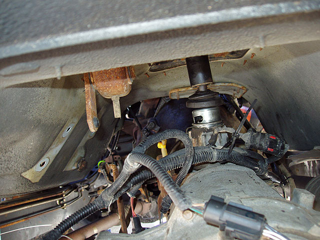
23. Lift driver side carpet and remove 4 t-case shifter link bracket bolts from the transmission tunnel and set aside. Remove bracket and set aside (This would be a good time to install the new shifter linkage bushing kit onto the bracket detailed in a Jeep TJ service bulletin regarding this component). Shift the t-case into 4 high so link can be popped out of t-case shifter lever and pop the shift linkage out of the t-case lever and let hang down. A brake spoon works well as a lever here since this is a click-fit into the urethane bushing holding the linkage into the lever. |
 |
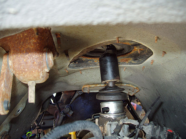
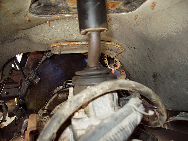
24. Shift trans into neutral, remove shift tower boot (not shift lever boot!), and slide up shifter lever. Dolly in under the driver side of the Jeep and reach both arms up over trans/t-case & feel for top of shift tower where shifter enters trans. There is a spring loaded cup (retainer) that is bayonet attached (like a taillight bulb). You can press down and fee it spring back - you can only feel it, not see it. Looking up at the trans from the dolly, press in the retainer until you can give it a quarter turn CLOCKWISE to release it. You'll know when it springs up out of the way. Push shift lever up and OUT OF THE TOWER to prevent damage when the trans is removed. Let end of shifter rest on top of trans. Use a piece of bungee cord or surgical tubing to tie off the shifter knob to the steering wheel to keep it out of the way. |
 |
25. Set up inside the rear prop shaft tunnel & locate and disconnect all harnesses from the trans/t-case assembly & let sit loose. Disconnect t-case vent hose & cap off vent with short piece of rubber tubing closed off with a zip tie. Support the trans/t-case assembly at the junction of the trans/t-case with the trans jack adapter/floor jack & jack up in place until it contacts then one more pump to unload the initial jack supporting the trans casting. The orientation of the main jack with the adapter should be such that it roles along a front to rear axis of the vehicle. Remove the initial supporting jack. Secure chain over the top of the transmission/t-case assembly and TIGHTEN . DANGER: FAILURE TO DO THIS STEP WILL RESULT IN SERIOUS INJURY WHEN THE TRANS IS DISCONNECTED FROM THE REAR OF THE ENGINE AND FALLS OVER ON YOU. |
 |
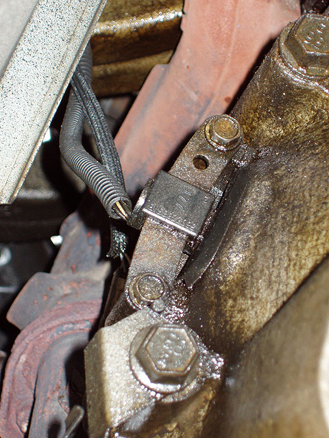
26. Remove 2 inspection plate cover screws (one above starter and one in a similar position on the driver's side). They are accessible from the engine side of the transmission. Remove 2 large bolts with nuts holding the lower portion of the inspection plate cover in place - put s nuts back on bolts after removal, and set aside, each on their corresponding side of the vehicle. Note: all transmission bolts are different lengths and have specific placement on the bell housing - best to note their size and keep them set aside on separate sides of the vehicle. Two lowest ones have nuts and two shortest ones are at the top of the bell housing. Of the two remaining on the driver's side one has a bracket to guide the slave cylinder hydraulic line and this is the lower one. On the passenger side, one has a zip tie attachment loop (lower or middle one) and one does not. Cut the zip tie only , leaving the loop in tact and remove the bolt/bracket and set aside. The bracket will be used to guide the trans/t-case harness upon reassembly. |
 |
27. Wrench clearance is tight on the passenger side but combination of access points allows a small 3/8" ratchet to be swung enough to free these bolts. When doing this part of the procedure you want the transmission/engine joint to be somewhat neutrally loaded, meaning that the trans is pretty much inline with the engine and is neither tilted up or down with respect to the engine. Once all the bolts are removed, raise the trans jack a little , use a brake spoon, and pry apart the engine and bell housing. It will take about 1/2" to 3/4" of separation to clear the registration pins on the engine block (these are used to realign the trans later after the splines have been re-engaged). Slide the trans and jack rearward by rolling the jack. You'll probably experience the trans shift somewhat on the jack. This is why you had to tighten the chain over the top of the adapter. Lower the jack somewhat, and continue rolling rearward to gain access to the clutch and flywheel. About 2 feet of clearance between engine and bell housing should do. |
 |
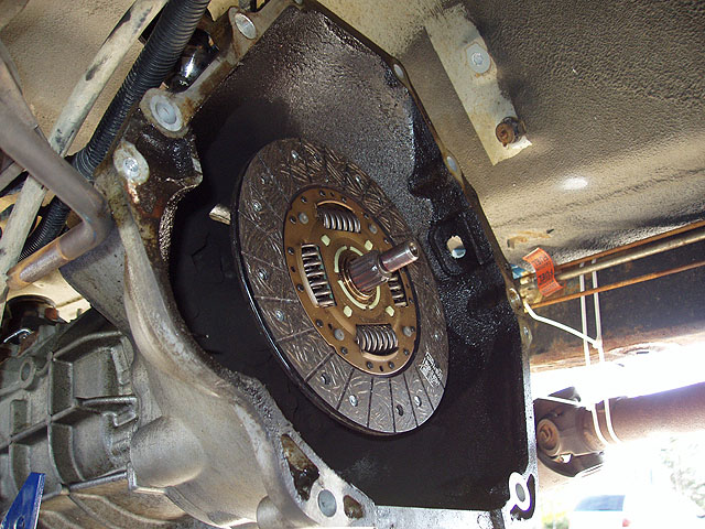
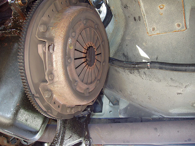
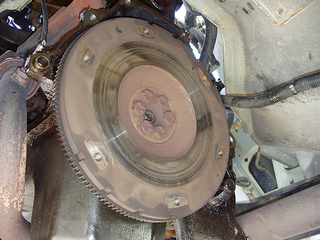
28. Flywheel and pressure plate exposed. Note wear on the actuating fingers. Eventually these will wear through if the throwout bearing seizes and you'll lose the ability to disengage the clutch. |
 |
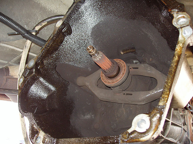
29. Release (throwout) bearing and clutch "fork" exposed. Remove clutch fork/throwout bearing from inside bell housing by sliding throwout bearing along trans input shaft sleeve until it is free. Set this aside until you're ready to replace. Also note the "grease" on the inside of the bell housing. This is a symptom of a leaky rear main seal on the engine. This TJ has about 140,000 miles on it and probably wasn't maintained by its previous owner as we would have hoped. As the engine oil leaks, it hits the back side of the flywheel, spinning to the outside edge and depositing it on the bell housing walls. Ironically the clutch didn't have any oil contact, so we're only looking at replacing the engine on this when it actually blows. The engine is not burning oil at this point, so we're playing a waiting game. |
 |
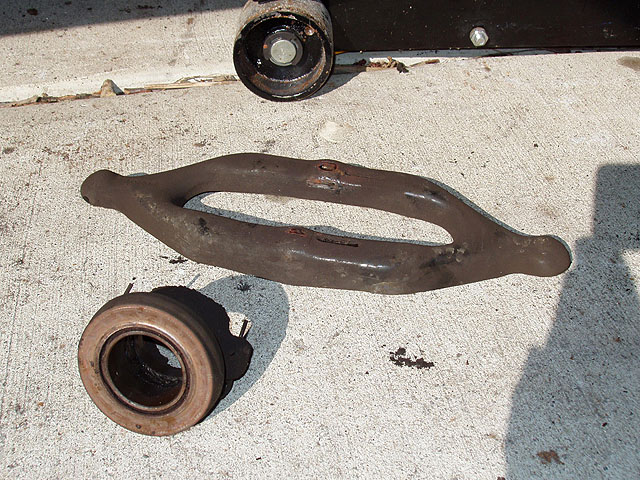
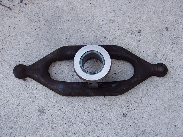
30. Note the depression (groove) on the face of the throwout bearing where it contacted the pressure plate. A new one has a flat precision machined surface which will be shown in photos later on during this procedure. Behind this plate is a set of ball bearings which spin freely during the clutch pedal depression phase of shifting. The clutch disk sits between the ring of the pressure plate and the flywheel by high spring tension of the pressure plate. The throwout bearing allows a stationary mechanism (the clutch fork) to depress the springs of the pressure plate which is spinning at engine RPM. This one was barely spinning freely, but it was still loose and made a lot of noise as the clutch was disengaged. I had a Pontiac Sunbird in which the throwout bearing seized. The bearing then spent time machining the fingers off the pressure plate a little at a time until there was nothing left. The next depression of the clutch pedal at that point is the last until the driveline is pulled and all this stuff replaced. |
 |
31. Loosen all the bolts securing the pressure plate to the flywheel and set aside. To gradually remove the spring pressure, loosen each a little at a time until the clutch disk drops off-center within the assembly. Then remove all these bolts, grab the pressure plate, and disk and remove them. Note the rivets (the silvery ones) on this disk. These were just in contact with the flywheel and the pressure plate. Symptom of this level of wear is that right after you've shifted into 3rd or 4th gear, and step on the gas, the engine RPM quickly ramps up without a corresponding increase in speed - the clutch is slipping. At this level of wear, replacement (by yourself or professionally) is inevitable. |
 |
32. Note the groove worn into the pressure plate by the rivets. The flywheel wasn't as bad so we simply resurfaced it with 60 grit sanding sponge (the manual recommended 150 grit emery cloth). |
 |
33. Note the notches in the flywheel used to transmit crankshaft position to the PCM through the crankshaft position sensor. |
 |
34. Using the supplied alignment tool, align the splines of the clutch disk and tool, and the pilot into the pilot bearing. NOTE: there are two sides to this disk - a flywheel side and a trans side. If it is not explicitly stamped on the new disk, compare to the original by looking along the edge. The spring plate of the clutch disk sticks out further on one side than it does on the other. Our original was stamped, the new one was not so we did this comparison before installation. We didn't replace our pilot bearing because it was still in pretty good shape. It does little more than slip the pilot when the clutch is disengaged so the synchros in the trans can do their job. We simply greased ours and left it in place. Removal will require a pilot bearing removal tool which we didn't have. |
 |
35. Also check that the clutch slides freely on the splines of the transmission input shaft without binding. It's more a check at this point than something that needs to be remedied. Replace the clutch disk onto the flywheel using the alignment tool and have your helper hold it in place while you get the pressure plate placed. |
 |
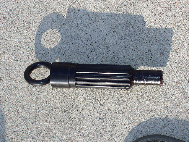
36. Closeup of the alignment tool. Note how it looks like the input shaft of the transmission. |
 |
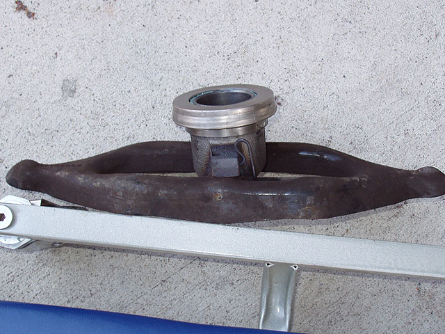
37. Closeup of the new throwout bearing mounted on the clutch fork. Note the smooth machined and precision ground surface of the contact plate. After the pressure plate is put back in place and bolts replaced, double check the centering of the disk via the alignment tool by eyeing the spacing between the tool and all the fingers of the new pressure plate. At this point the disk is still somewhat loose and can be slid around until centered. After checking and readjusting the center, tighten them in a star pattern until the pressure plate is contacting the flywheel at all points. Torque the bolts to 30 foot pounds. REMOVE THE INSTALLATION TOOL or you'll never get the trans docked in the clutch splines and pilot bearing. This is not something you want to discover after you've expended the energy to roll the trans forward for docking with the engine. |
 |
38. Replace the clutch fork taking care to thinly coat the ball and socket that the fork contacts on the passenger side with Mobil 1 grease. Also thinly coat the sleeve of the input shaft that the throwout bearing slides along. This will reduce friction and binding and result in smooth clutch operation. At this point you are ready to rendezvous and dock the transmission with the engine. Roll the trans/t-case assembly on the jack forward and align it roughly with the axis of the vehicle, jack the trans up until it looks approximately aligned. The pilot and bearing is your best friend at this stage of the procedure. |
 |
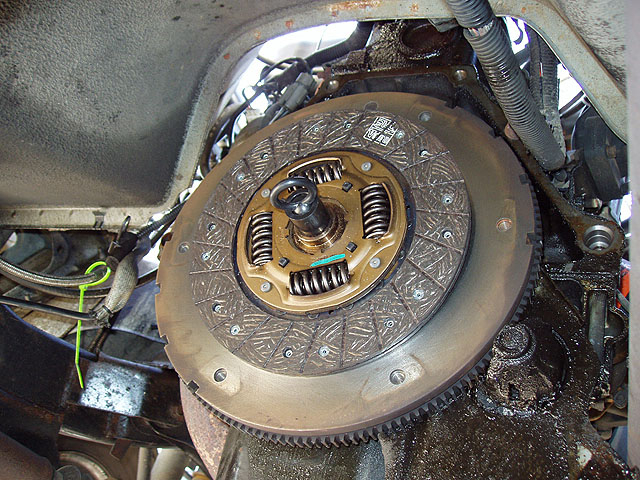
39. The transmission docked with the engine. This is not a step that can be easily described. Once you have the rough alignment in the previous step, continue to roll the trans forward slowly , adjusting the "roll knob" on the adapter until the two registration pins align with the corresponding holes in the bell housing. You may have to do some wiggling and rocking of the trans to get final "hard dock" to take place. Leaving the trans in neutral from a previous step will allow the splines of the input shaft to self align to allow docking to proceed smoothly. |
 |
 |
 |
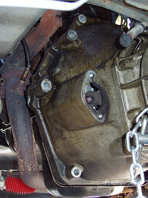
| 40. You can see the shifter, not yet reinstalled, the t-case vent blocking tube and one of the holes for mounting bolts at the top of the trans in this photo. |
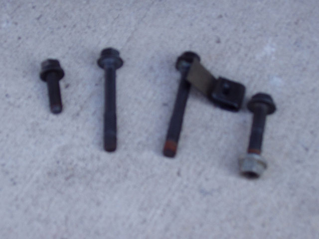
41. Bolts for the driver's side |
42. Good shot of the 4 mounting holes on the driver's side |
 |
 |
 |
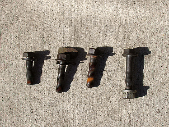
| 43. Bolts for the passenger side. |
44. Best shots we could get of the mounting holes on the passenger side. The starter and exhaust is on this side so working area is much tighter. |
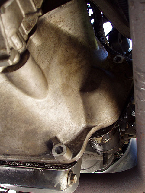
45. The "bulge" in the bell housing is for the business end of the starter where it engages the flywheel. |
 |
46. Replace 8 transmission mounting bolts in their previous locations as well as the inspection plate screws, taking care not to strip the latter going in (they are sheet metal screws and not conventionally threaded. It is impossible to get a torque wrench up here so "as snug as you can them and a little more" is the order of the day. Factory spec for these is 25 foot pounds. Some good views up the transmission tunnel looking toward the engine. Note the placement of wiring harnesses, and the location of the shift tower, with shifter relocated but not retained. |
 |
47. At this point the second jack was cranked up under the transmission case casting as in a prior step before we removed the trans, and the transmission jack and adapter was removed to making working on reassembly easier. This is a good place in the procedure to get all the harnesses reconnected along with the transfer case vent, and the zip tie restraining the harness on the passenger side trans bolt bracket which was previously cut off. |
 |
48. After the shifter is realigned (you'll feel it drop into place),
depress the cup and spring retainer as in the removal step above, and turn it a partial turn COUNTERCLOCKWISE until it stops and release.
It is now retained. This again is a "by feel" step rather than a "by sight" so you may need a couple of attempts. |
 |
 |
 |
| 49. After the retainer is locked slip the shift tower boot back in place and snap it around the shift tower. |
50. Untie the slave cylinder from its temporary holding place on the frame and re-install it using the two nutted studs that were saved in the removal step taking care to slip the hydraulic line into the clip on the driver's side transmission bolt noted in a previous step. |
51. Untie the crankshaft position sensor from its temporary holding place on the fuel line, carefully push it into the rubber grommet on the bell housing and re-install it using the bolts that were set aside in the removal step. |
 |
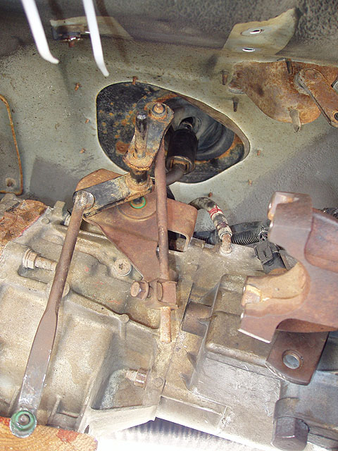
52. Reinstall the transfer case shift bracket at its location in the underside of the transmission tunnel on the driver's side. If you didn't install the t-case linkage bulletin repair kit earlier, now is a good time to do that. Follow the instructions supplied with the kit to replace the boot and bushing on the shift bracket. Hook the appropriate link to the t-case shifter lever and the other one into the transfer case shift arm. A channel lock pliers helps to press these back into their urethane bushings. A little Mobil 1 grease on the arm and the bushing doesn't hurt either! In this photo, the arm with the adjuster on it goes into the shifter lever hanging down near the upper right corner of the photo. The other arm without the adjuster goes into the transfer case shift arm on the transfer case to the left of this photo. |
 |
53. Reconnect the rear propeller shaft taking care to line up the paint marks you created prior to the removal step. Lacking LocTite for this step we used hi-temp RTV on the threads (the same kind you use when re-sealing the differentials after drain and replace service). Tighten the bolts snug - they have a pretty solid stop, but don't over tighten. We used a 1/4" drive ratchet handle to avoid applying too much torque. |
 |
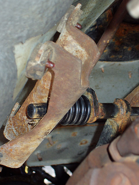
54. Untie the front propeller shaft and re-connect it to the front output of the transfer case, taking care to line up the paint marks you created prior to the removal step. In the case of both propeller shafts wiggling them back and forth in the yokes to get them seated is recommended before tightening the bolts. For this shaft due to tight clearances we used a ratcheting box wrench since we couldn't get a socket in there. |
 |
 |
 |
| 55. Here is a shot showing the t-case shift lever with the service bulleting kit installed. |
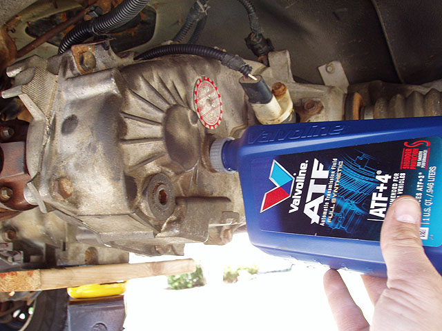
56. Fill the transfer case with 1 quart of ATF-4 Synthetic. One of the tops off a gear lube bottle makes this job pretty much spill free. |
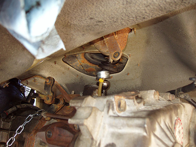
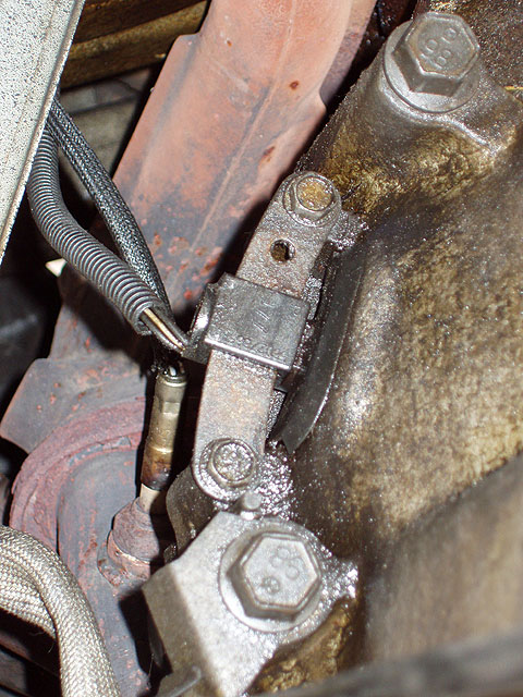
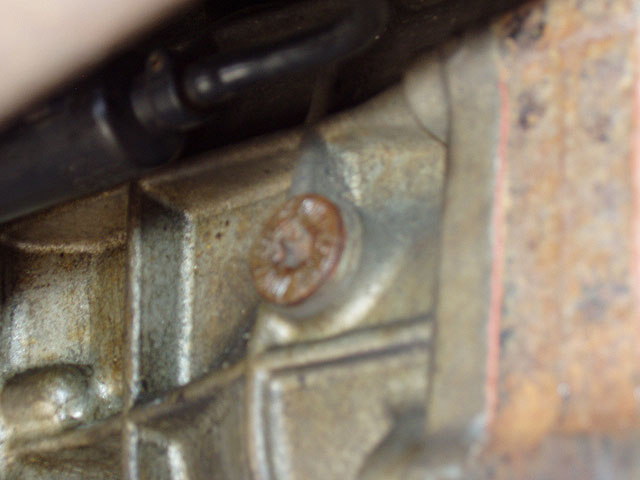
57. You're now ready to fill the trans, but this photo serves as a WARNING: this is NOT the fill plug. This plug marked in embossed letters DO NOT REMOVE on the driver's side is not it. It has a torx head and is the only one on the trans that does so. |
 |
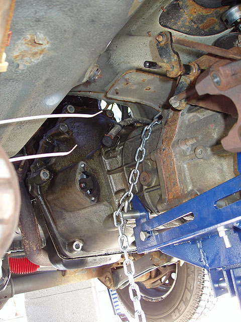
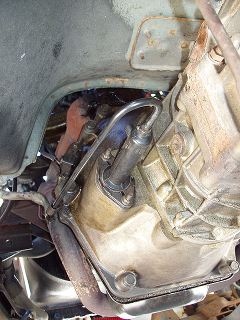
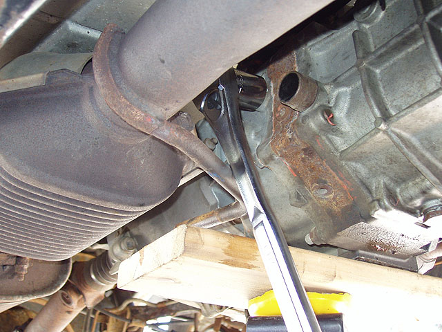
58. The fill plug is on the passenger side as shown by the ratchet position in this photo and the ratchet removed in the photo after that. |
 |
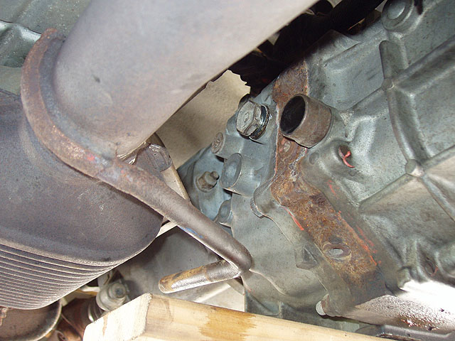
59. Note the location of the fill plug above and to the rear of the reverse switch. Also note the missing wires on the reverse switch. These got caught on the exhaust when we lowered the trans and ripped out. It's a two wire switch and this being on a Sunday we couldn't get to a dealer to replace it. That will be a later project. Lesson learned: make sure these wires are out of the way when the trans is being lowered. This is the only wired component of the trans/t-case assembly that the wiring is on a pigtail. All others are solidly mounted and protected when the harness is unplugged. |
 |
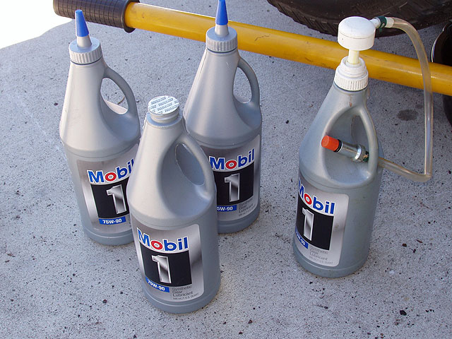
60. Don't refill the trans with the fluid recommended in the '97 owner's manual. DaimlerChrysler found out about a year after this was released that something in that compound caused pitting and premature failure in the synchros. An excerpt from another forum to back this up: "The 5 speed tranny uses brass synchros and the Owner's Manual says to use GL-5 gear lube. GL-5 has a sulfur base and will eat the brass." An alternative, Redline MT90 is recommended. We did a little research and learned that Mobil 1 75W-90 is equivalent to Redline MT-90, costs about the same and was the best stuff for the trans that was rated for this duty. Service manual calls for 3.3 liters. We used 4 because with the lube pump we used you can't drain the bottles completely anyway. It took 4 full bottles to get 3.3 in the trans. The remainder in each was consolidated into a single bottle and saved for next time we service our diffs. (NOTE: you need this pump - there is no room for a funnel or even to get the bottles up in tight clearance and you have to pump and pump and pump to fill the trans. A very tedious process when you're so close to finished.) |
 |
61. Install the t-case cross member using the 4 bolts set aside during disassembly. Note the LocTite on the bolts. We used hi-temp RTV as a substitute on the threads before putting them back in. Factory torque spec on these 4 bolts is 24-44 foot pounds. |
 |
62. Note the position of the auxiliary jack, carrying the load of the driveline until we can get the skid plate back in place. |
 |
63. Install the skid plate back in place (this is a 2 person job), replacing the 6 skid plate bolts you removed in the removal step (and any washers if you corrected your driveline after a lift by lowering the skid plate). We used an impact set at about 50-60 foot pounds for these. This photo shows the cross member nuts being installed on the cross member studs sticking through the internal layer of the skid. (it's a 2 layer skid at this point). These nuts are torqued to 24-36 foot pounds. 15 hours later and we're DONE! Time to get the blocks out of the way, remove the jack stands and get the wheels back on the ground. |
 |
64. Lots of tools to clean up but otherwise, you're done! |
|